Su carrito de compras está vacío
 
English Polski Spanish 
Buscar un manual
 

(p.Ej. AA-V20EG JVC, ZX-7 Sony)
PayPal 1000+ rating Secure, Encrypted Checkout.
 
Usuarios conectados
Actualmente hay 5754 visitantes online.
Productos
Información
Destacado
Inicio >> RICOH >> VT6000 Manual de Servicio
 
 0 artículo(s) en Su carrito 

RICOH VT6000
Manual de Servicio


¡Twitee acerca de este producto y obtenga $1.00 de crédito en la tienda para uso!
  • Contiene diagramas del circuito
  • Descargable
  • Formato PDF
  • Manual completo
  • Idiomas: English
Precio: $4.99

Descripción del RICOH VT6000 Manual de Servicio

Manual de servicio completo en formato digital (archivo PDF). Los manuales de servicio por lo general contienen diagramas de circuitos, tarjetas de circuitos impresos, consejos para reparación, diagramas de cableado, diagramas de bloque y lista de refacciones. El Manual de Servicio (a veces llamado Manual de Reparación) es usado principalmente por los técnicos.

Si tan solo quiere saber cómo utilizar su televisión, reproductor de vídeo, reproductor de mp3, etc. Quizá lo que necesita es el Manual del Propietario. Después de colocar la orden le enviaremos las instrucciones de descarga a su dirección de e-mail.

The manual is available in languages:

Not yet ready
You must purchase it first

Opiniones de los clientes
No hay comentarios de productos.

TEXT_PDF_SNIPPET
29 January 1998

MASTER FEED

5. REPLACEMENT AND ADJUSTMENT
5.1 MASTER FEED
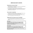
5.1.1 THERMAL HEAD VOLTAGE ADJUSTMENT
VR1

CN503

C228R500.WMF

Purpose:

To maintain the quality of masters and to extend the life of the thermal head.

Adjustment Standard: There are two steps. 1) The output voltage for the thermal head from the power supply unit must be 22.5 volts (r 0.5). 2) The output from the DC/DC converter board is different from one thermal head to another. Refer to the voltage value (X) on the thermal head decal. The output should be between "X-0.1" and "X" volts. NOTE: This adjustment is always required when the thermal head or power supply unit is replaced. 1. Turn off the main switch and remove the paper exit cover plate (4 screws). 2. Disconnect connector CN503 of the power supply unit. 3. Turn on the main switch, and access the SP mode and select output check mode (SP131) No. 41. 4. Press the Print Start key to apply thermal head voltage continuously (60 seconds). 5. Check the voltage between CN503-15 and CN503-12. If the voltage is not 22.5 volts (r 0.5), turn VR1 on the power supply board to adjust the voltage.

Replacement Adjustment

5-1

Quizás también quiera comprar

$4.99

VT6000 RICOH
Manual de Usuario

Manual del propietario completo en formato digital. El manual estará disponible para descarga como …
>
Parse Time: 0.149 - Number of Queries: 100 - Query Time: 0.041